12May2009 – old stuff that may still be useful

Aaahhh, toys. Few things are sweeter to hack. I started at age 4 by smashing all my squirt guns open to get the pumps and hoses inside. Toys are great hacking fodder because:
- they’re cheap to obtain: trash, dollar store, Winners, garage sales, etc
- you can learn a ton from observing optimizations in their construction, which are usually due to cost sensitivity, but sometimes due to ease of assembly
- they often offer complex functionality (that would otherwise cost you an arm and a leg) that can be easily repurposed such as speech modules, gear motors, etc
The point of this post is to illustrate how to programmatically “push buttons” on a device using the Arduino.

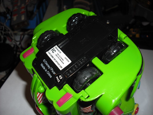
Here is a pretty standard R/C toy that I thought would be cool to drive via an Arduino. You can apply a similar approach to driving digital cameras, coffee makers, telephones, etc. Most things with momentary-contact switches are fair game. Here’s basically how it works:
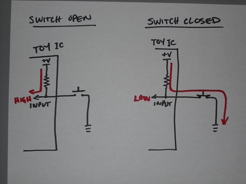
The toy integrated circuit on the left is looking at an input from a switch. When the switch is open, the pullup resistor “pulls up” that input to a logic high, so the IC knows nobody is pressing the switch. On the right the closed switch sinks current through the weak pullup resistor to ground, causing the IC input to now see a logic low value. A ha! Someone has pressed the button. Drive the car forward.
Just so we know what we get out of this at the other end I should mention that this toy employs a differential-drive system, i.e. independent motor drive for each side which allows steering by running one side more or less than the other.
The very simple remote features two buttons that control each motor in both forward and reverse directions

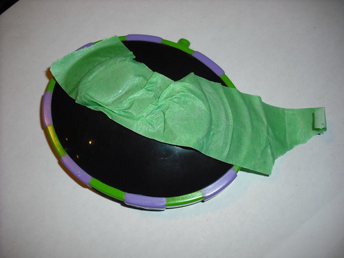
So that’s 4 buttons in all that we want to control. We can leave the actual “car” intact (for now) since it gets its marching orders from the remote regardless of what or whom is pushing the buttons. Let’s crack this baby open:
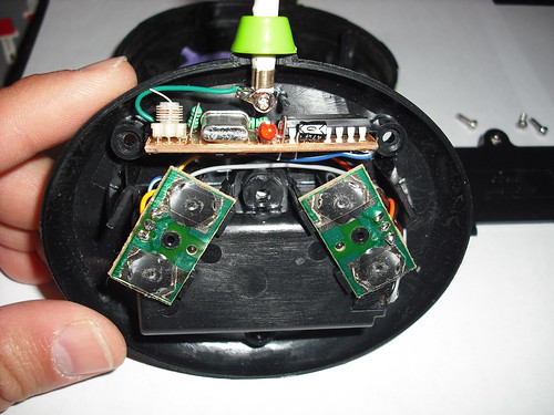
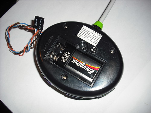
sweet simplicity: main board with crystal (49MHz), inductors and RF stuff, but don’t worry about that, although it is sort of tempting to look up datasheets on obvious parts like this big DIP IC which turns out to be a TX2C ATS302T five-function transmitter chip. You can bet its counterpart receiver is in the car. Right now, we’re more interested in these smaller boards with the snap buttons on them
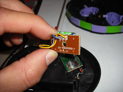
Using a multimeter on continuity function with one probe on the negative battery terminal you can explore what these three wires on the switch board connect to. Sure enough the middle (gray) one is ground, so that must make these other two wires the IC inputs. Powering up the remote and measuring the voltage at J1 and J3 above I saw that those pads are sitting around +9V (battery voltage) so they are almost certainly being pulled up by a resistor (sometimes integral to the IC). All we need to do here then is yank those lines down to ground. I didn’t do that directly with the Arduino because it’s running at +5V and the remote here was running at +9V, so they have different understandings of what constitutes a logic HIGH. Enter the field effect transistor (FET)
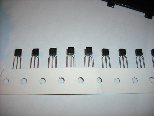
These are 2N7000 N-channel FETs. Very cheap, very useful. The FET works as an auxiliary switch
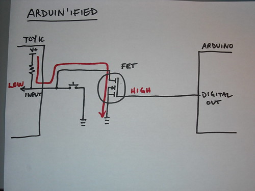
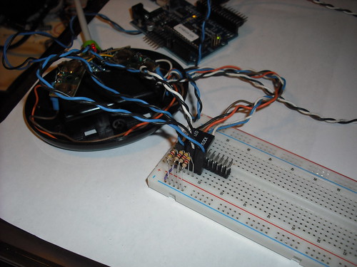
One of my design goals when doing these hacks is to preserve the functionality of the original switch as shown in the design above. So I breadboarded that ’cause it’s been a while since the last time I did this:

and that seemed to work ok, so I busted out 3 more FETs and figure out how to solder them into the toy such that
- they would fit
- I wouldn’t need a circuit board
- and they wouldn’t interfere with the buttons
See, this appears to be going great:
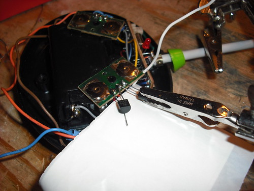
But it’s late so I get the FET turned around, and that’s pin 3, not pin 1, so desolder and reattach, but then I realized I hadn’t left enough leg on the FET to bend it around underneath the board so I desolder again and use a new FET, but heating the board that many times causes a pad on the PCB to lift, so I scrape off some green, so I can solder to copper and it’s all starting to look better.
Heat shrink tubing on (didn’t forget to put it over the wire before soldering). McGiver’d the buttons with some tape so they didn’t fall out during reassembly
power up, and…
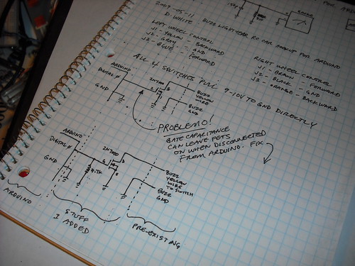
Something’s wrong. The little “transmit” LED is constantly on. Hmmm. Buttons jammed by case? No. Wait, the LED’s are sort of only half on now. Now they’re off. And on again. Fail? Opportunity for Further Thinking. What have I learned about FETs over the years? Turned on by a voltage at the gate. Have a lot of gate capacitance. Open inputs lead to unpredictable… oh yeah. I need pull-down resistors on my FET gates to keep them fully off when the Arduino is disconnected. Labbook:
That might be a stronger pull-down resistor than necessary (4.7K), so I try it out:
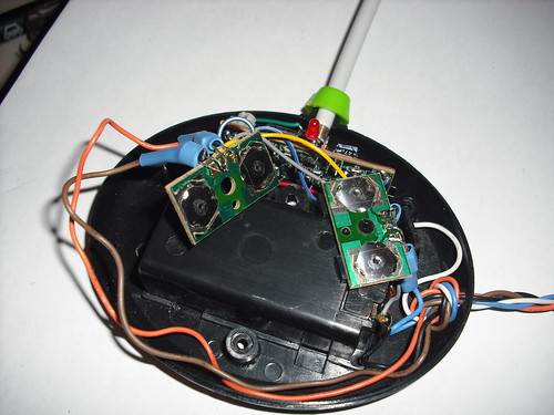
That’s much better. Now how to apply these resistors inside the case that is already neatly wired? Ugly hack time:
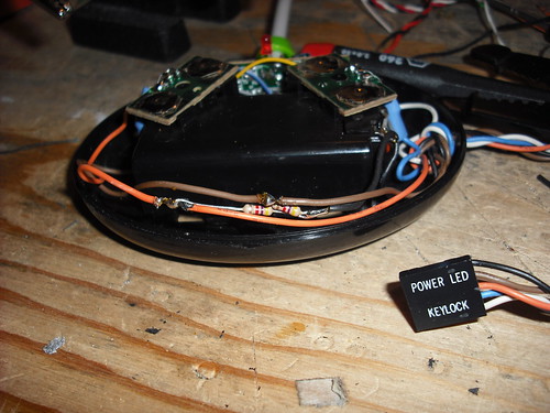
Burn insulation off wires to gate, haywire pull-downs to negative battery terminal. Not pretty, but… it works. Check before closing case:
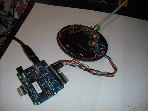
Still good. Wrap it up.
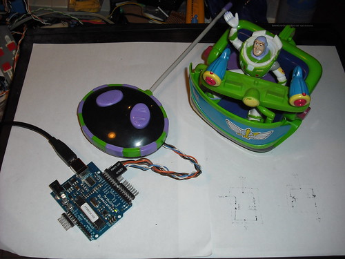
And finish a sketch (below) that has Buzz do a little shuffle and then spin in place. I’m sure one of my readers will suggest twitter-enabling the remote so we can drive buzz with tweets. I leave that as an exercise. Be sure to leave a comment telling what project/device you will use this approach on.
Notes in passing:
- The FCC site has a search tool that can provide a wealth of info on a device you are hacking. On the back cover of the remote control you’ll see “FCC ID No: P73KGRACER49A”, which you need to decode a bit. “P73” is the grantee code (i.e. the manufacturer), and the rest of the string is a product code “KGRACER49TA”. Which gives you the a result that includes the docs submitted by the manufacturer for testing, like a schematic or internal photos (look familiar?) and sometimes even the owner’s manual. This has also been very helpful in the past to determine the frequency of a found RF device.
- ESD kills FETs so try to stay grounded especially during winter
- The approach described above is not for switching large (and/or mains) currents, just logic levels. The laws of common sense completely apply here
Plug for our Arduino 201 – Get Motorin’ Meetup: if you liked this post, imagine how much fun it will be to meet up and actually make stuff instead of reading about making stuff. Please join us May 23. Seats are still available.
Make: out like a bandit
DW
Arduino code:
/*
Control toy rc remote via 2n7000 FET transistors with gates on pins 13 to 10.  A pin going HIGH is equivalent to a button press on the remote
Author: Darin White
Date: 2009-05-11
*/

int leftBackPin = 13;                // FET connected to digital pin 13
int leftForwPin = 12;                // FET connected to digital pin 12
int rghtBackPin = 11;              // etc
int rghtForwPin = 10;

void setup()                    // run once, when the sketch starts
{
  pinMode(leftBackPin, OUTPUT);      // sets the digital pin as output
  pinMode(leftForwPin, OUTPUT);      // sets the digital pin as output
  pinMode(rghtBackPin, OUTPUT);      // sets the digital pin as output
  pinMode(rghtForwPin, OUTPUT);      // sets the digital pin as output

  digitalWrite(leftBackPin, LOW);      // both motors off
  digitalWrite(leftForwPin, LOW);
  digitalWrite(rghtBackPin, LOW);
  digitalWrite(rghtForwPin, LOW);
}

void loop()                     // run over and over again
{
  for (int i=0;i<8;i++) {
    // shuffle forward, first left then right side
    digitalWrite(leftForwPin, HIGH);
    delay(150);
    digitalWrite(leftForwPin, LOW);
    delay(1000);

    digitalWrite(rghtForwPin, HIGH);
    delay(150);
    digitalWrite(rghtForwPin, LOW);
    delay(1000);
  }

  // now spin in place
  digitalWrite(rghtForwPin, HIGH);
  digitalWrite(leftBackPin, HIGH);
  delay(3000);
  digitalWrite(rghtForwPin, LOW);
  digitalWrite(leftBackPin, LOW);
  delay(2000);
}