15May2009 – old stuff that may still be useful
Somebody was asking about limit switches today. We were talking about driving motors and my upcoming Arduino 201 – Get Motorin’ (May 23) meetup and he mentioned one of his applications required limit switches that signal a motor to stop running when something hits a certain limit of travel.
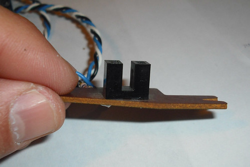
These get used in all sorts of equipment including your flatbed scanner, disk and DVD drive to stop something (scanning head, disk/DVD read heads) once it moves to a certain position. Hey, you might have one under your index finger right now: the track wheel on a typical computer mouse is connected to a slotted wheel that uses an opto-interrupt switch (shown above) to detect mouse wheeling. That’s not a limit-switch application, but the same sensor is involved. This is a non-contact switch. When an opaque flap enters the U-shaped black sensor above, it breaks the infrared beam of light and trips the switch. No touching required. This particular switch came out of a dumpster-found line printer. You might use such a switch in:
- your homebrew CNC machine so the X, Y, and Z axis all know where “home” is
- a tachometer on your pottery wheel so you know how fast it is spinning
- as a safety switch in your SMT toaster reflow oven to make sure the door is closed
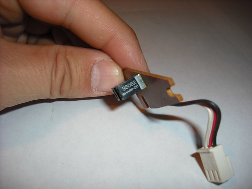
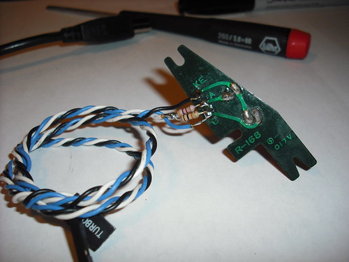
Once again, we see a nicely-screened part number here along with the manufacturer (Sharp). A cursory google search didn’t turn up anything meaningful like a datasheet, but it’s not really necessary. We already have the general idea of how these work from our earlier look at a reflective IR sensor and this is really just a variation. Rather than the IR light bouncing off something and back to the receiver, it just shines directly on it, waiting for something to interrupt the beam.
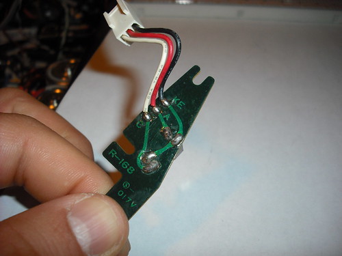
Flipping the board over, we see the nice PCB designers have marked it up to help us. Some educated guesses would be:
- KE – K==cathode(LED) and E== emitter(on IR NPN transistor) – so we reckon this goes to ground
- A==anode(LED) so this will go to +5V, but through a resistor to limit current
- C==collector(on IR NPN transistor), which we’ll add a pull-up resistor to and also watch as the output
Looks something like this:
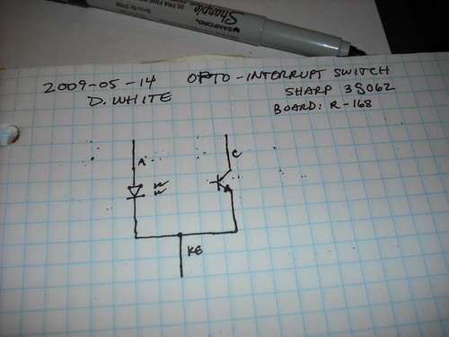
So we’ll just need to add a couple of resistors to make this part useful to us:

Let’s try it on the breadboard before committing to solder.
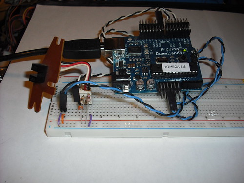
And it checks out with the voltmeter. Unblocked the output to pin 8 is 0.22V and with a hunk of cardboard inside the U, breaking the beam the output is 5.12V. Now try this little sketch (below) to light the LED on pin 13 when the switch is blocked. Hey that works too. Time for solder and some new wire:
And another test
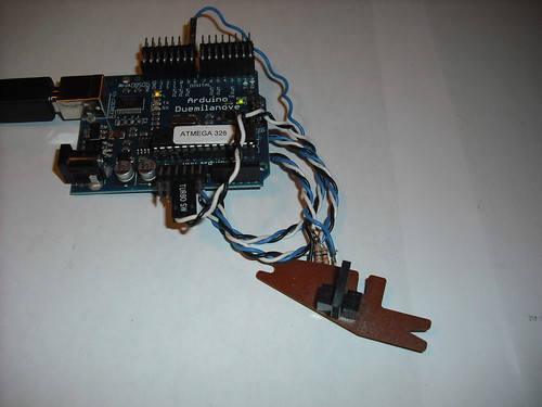
That’s a hunk of plastic stuck in the U to block the beam, and sure enough, the pin 13 LED on the Arduino is lit. Success.
Notes in passing:
- not everything that is visibly opaque is also opaque in the IR part of the spectrum, especially some black plastics. Keep that in mind when choosing your interrupter flap
- ambient light isn’t as much of a problem here as with the reflective IR sensor, but where possible it’s good to mount these out of direct light on your project
And two more things:
- Thanks go out to our friends shardy and company at hacklab.to for kindly agreeing to meet with us next Sunday (May 24) at their Toronto digs so we can talk about the ins and outs of setting up a working space.
- Thanks also to Adafruit Industries and Solarbotics for kicking in some motor drivers in support of my upcoming Arduino 201 – Get Motorin’ meetup.
Make: a new friend
DW
Arduino code:
/*
Demonstrate IR interrupt opto switch
Author: Darin White
Date: 2009-05-14
*/

int swPin = 8;     // input
int LEDPin = 13; // output

void setup()                    // run once, when the sketch starts
{
  pinMode(LEDPin, OUTPUT);      // sets the digital pin as output
}

void loop()                     // run over and over again
{
  if (digitalRead(swPin)) {
     digitalWrite(LEDPin, HIGH);
     delay(300);
  }
  else {
     digitalWrite(LEDPin, LOW);
  }
}
This is a great tutorial! Just what I was looking for.
I do have one question, can you tell me what size resistors you used? I think I see a 10k on the +5v side but can’t make out the other one.
Thanks!!!!