A funny thing happened last week on the way to meet-the-teacher night at Sir John A. MacDonald high school (SJAM, as we call it). Speaking with Arden’s tech teacher, Dean Henderson, I asked if his shop had any CNC-enabled machining tools. He mentioned they had both a Torcam lathe and a mill, but no software to run them. The maker in me could not resist that challenge. We exchanged a few emails, looping in my black-belt-maker-ninja buddy, Mr. James Bastow, and the two of us were off to high school this morning. Sorta like a tech version of 21 Jump Street.
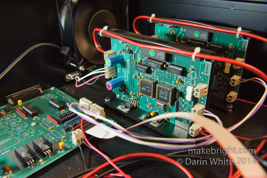
We cracked open the controller box for the lathe and found pristine electronics, not even dusty. SJAM inherited this gear from another school and the asset tags read 2002. The motor driver board above (right) is silk-screened with “1994” so this rig is likely 20 years old. Socketed chips and through-hole parts on these boards are a dead giveaway of the era. The assessment continued…
Long-time readers will recall I built my own 3-axis mill from scratch years ago to mill circuit boards. I totally caught the CNC bug the first time I saw my machine trace out a circuit that I had designed in software. It’s mesmerizing.
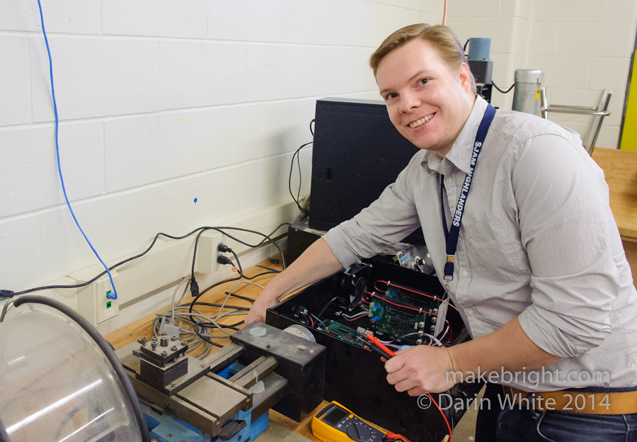
Here’s James Bastow, President of kwartzlab, the best damned makerspace around. James and I met as part of the team founding kwartzlab and just coincidentally both worked at BlackBerry. James has the mad skillz when it comes to anything to do with electronics, fabrication… pretty much anything.
This box is the key piece to the whole equation. It sits between the [lathe|mill] and the PC that drives it. We needed to figure out if it was DOA and then do a little reverse engineering.
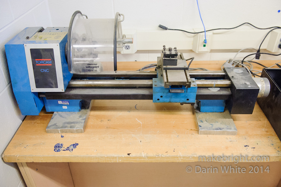
Here’s the lathe. This is pretty typical of our average bench-top machine shop lathe, except that instead of hand-wheels or geared feed mechanism to move the cutting tool, there are two large stepper motors to do that under computer control. You can see the coffee-cup-sized y-axis motor at the extreme right of this photo.
The lathe itself is super-heavy duty, as is the mill. The frames are made of one-inch thick steel and the mill weighs in around 500 lbs. That makes the prospect of getting this running so much sweeter. Far more robust than the typical modern hobbyist machine tools.
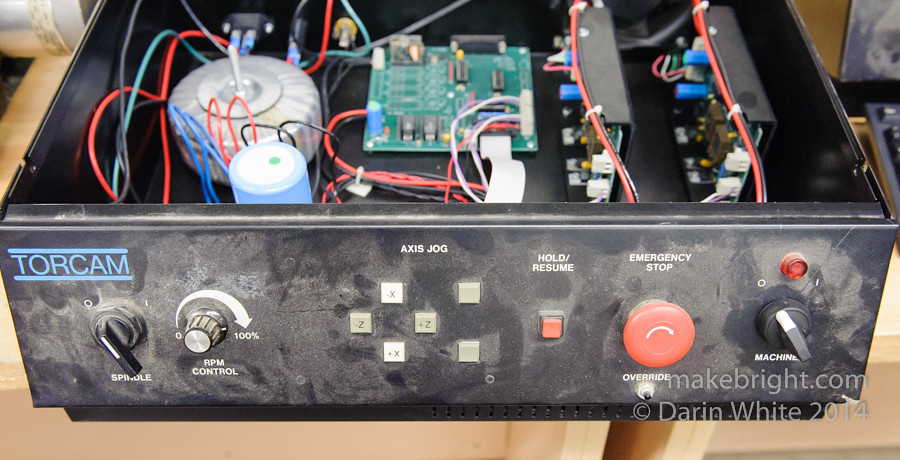
We initially tried to manually jog the machine with the front panel controls, but no joy.
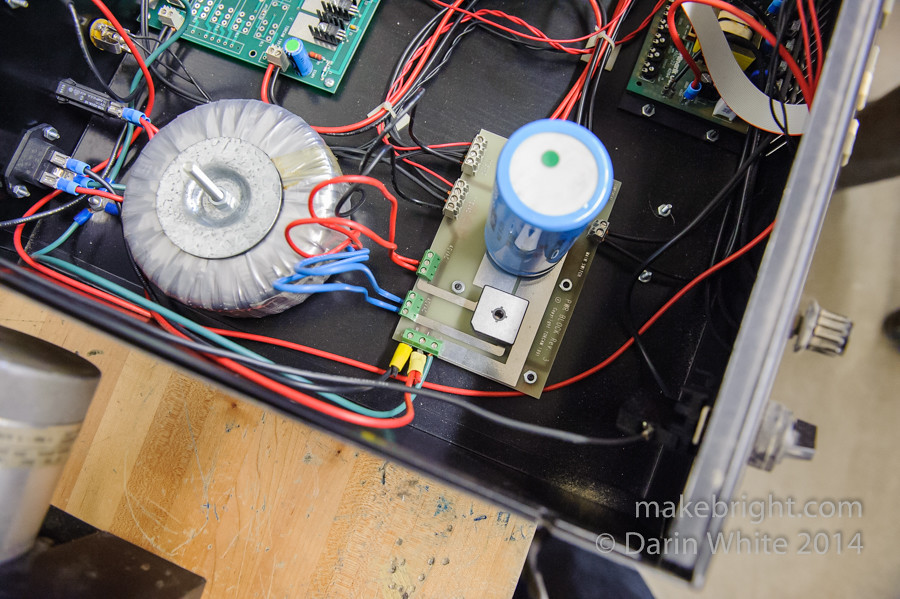
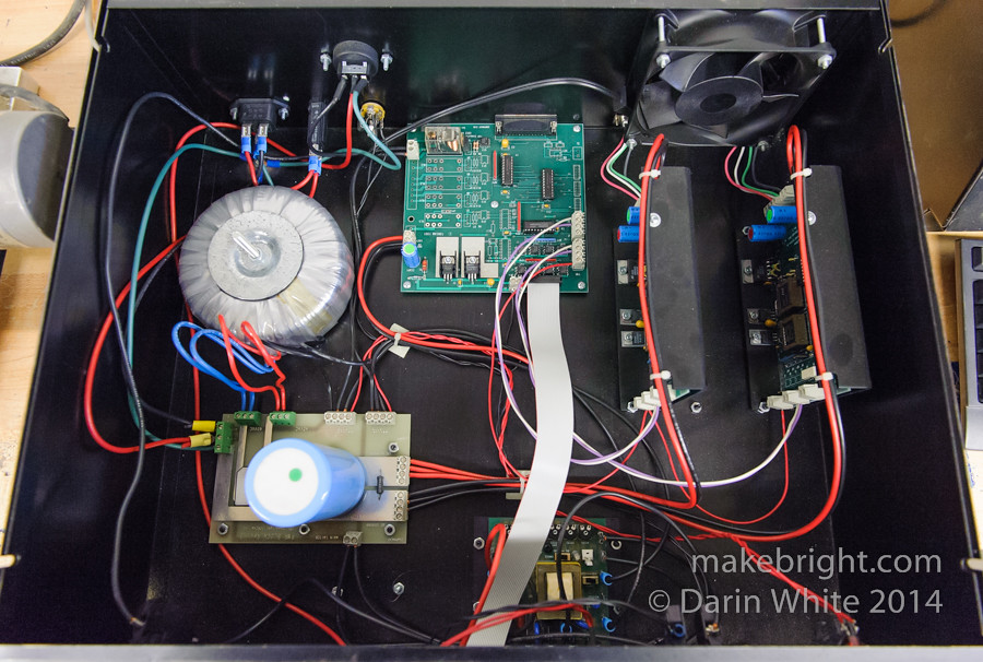
This giant toroid, capacitor, and rectifier bridge serve as the power supply to convert 110VAC to 34VDC to drive the motors at 4 amps each.
Right behind the control panel is the spindle speed controller.
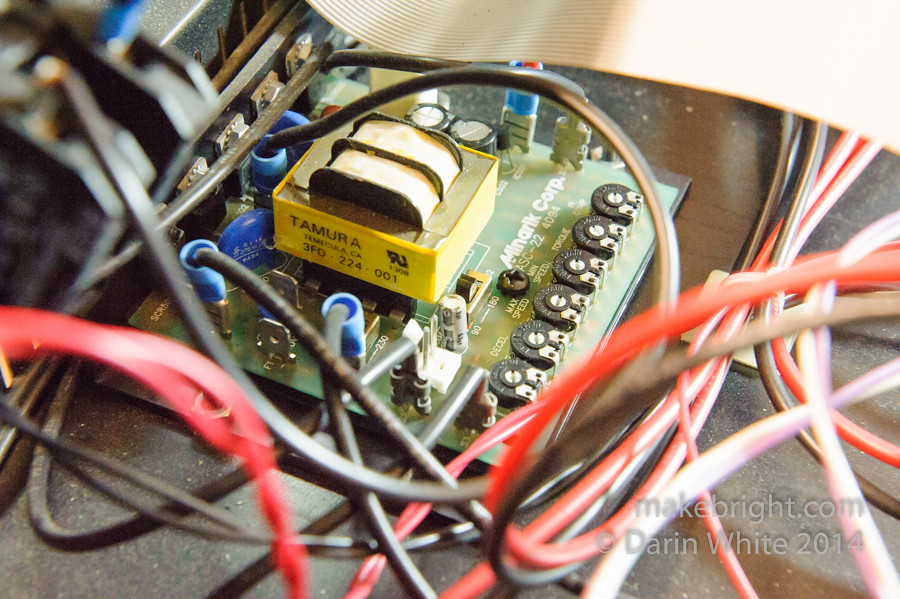
Those 6 potentiometers set parameters such as max speed and acceleration.
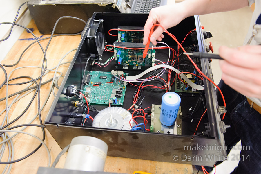
Some careful probing with a multimeter revealed that the two motor controller boards at the top of this photo are fairly independent of the rest of this rig. They appear to be bi-polar stepper motor drivers that take step and direction input lines and output 34 volts on 4 lines going out to the motors. Discovering this modularized design is encouraging because it opens up a number of different options for driving the lathe, including retro-fitting it. The more that can be salvaged from the original rig, the cheaper the refit cost.
There’s no budget for any of this, so time is all we can put into it.

James, Dean, and I had all independently googled Torcam prior to our visit and discovered that these rigs were built in Concord, Ontario by the now-defunct TOR Computerized Systems Inc. company. It seems like they were purchased by a number of school boards around Ontario. So if we can figure this out and document it, then maybe others can light up their tools as well.
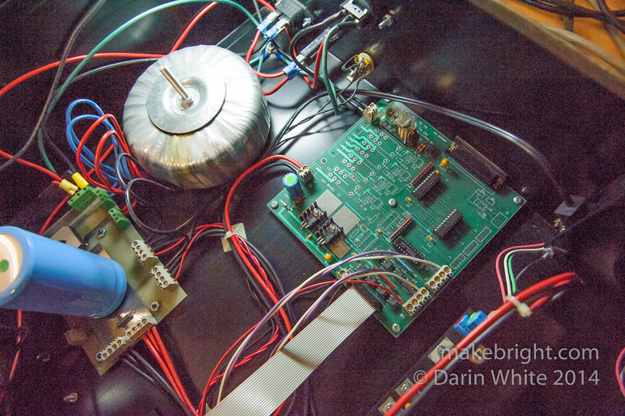
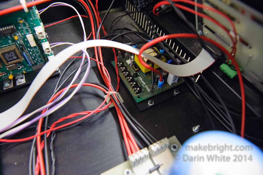
At right is the signal board. It basically contains buffers, opto-isolators, and linear regulators to output 5V logic powers supply. At the top you see the 25-pin D-sub connector, which connects via a parallel port cable to the PC.
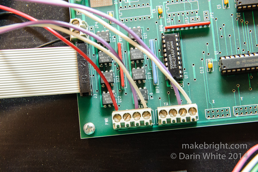
The 4N25 chips are the opto-isolators. The red wire feeds 5V to the opto-isolators on the motor control boards. The purple wires are the step lines. A 5V pulse on those lines cause the motor controller to step the motor a single step of rotation. The white wires cause the motor controller to drive the motor forwards or backwards depending if the line is high (5V) or low (ground).
James disconnected the purple step wire for the y-axis and rigged an over-ride jumper wire to fake out pulses on that line. With a tap of 5V on the y-axis step input…
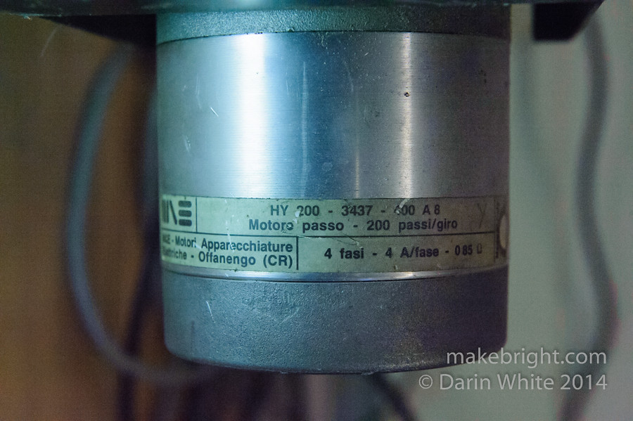
the motor moved ever so slightly! Very encouraging. Now to get this working as seamlessly as possible, I (yes, this is my part besides photography) need to reverse engineer the pinouts for the 25-pin logic connection between this box and the PC parallel port. Ideally we want to run this from Mach 3 software. We found Mach 3 on this PC from another machine in the shop…
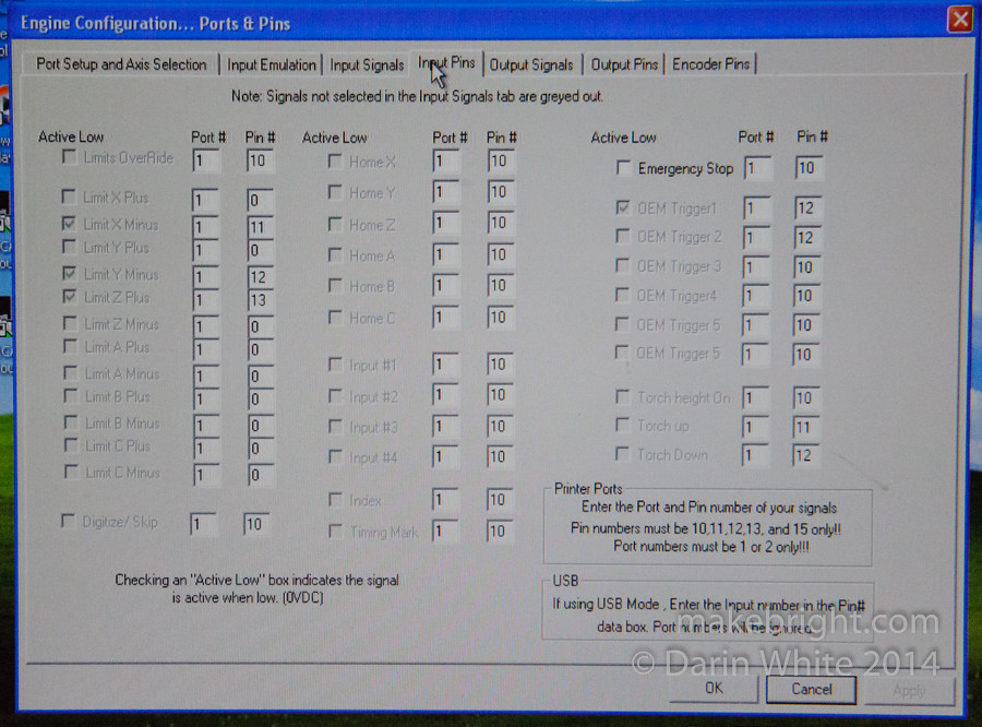
these configuration settings…
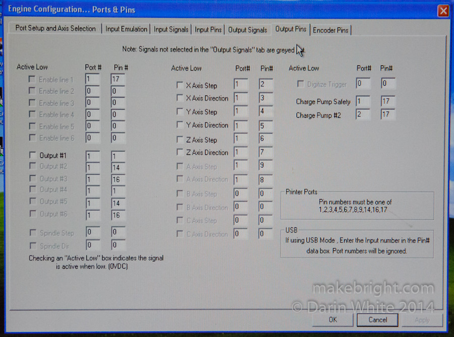
could be just the Rosetta Stone that will accelerate the reverse engineering.
So, fingers-crossed, I’ve got the box in the trunk of my car to muck around with at home. I’m going to grab a couple of bi-polar stepper motors from the junk box and hook them to this rig. Then I’m going to tweak the logic inputs and observe the results. Once we get that all mapped out, we can configure Mach 3 to drive this baby. Well, that’s the theory anyway. Let’s see how far I can get by investing a couple of hours.
DW
Very cool!
Pingback: Reverse engineering a TORCAM CNC lathe controller | makebright