Some people play golf. Other people love board games. Reverse engineering old electronics is my jam. I love it. It’s like a little puzzle and it completely absorbs me. I’m utterly free of function-guilt in these pursuits: I do it for fun.
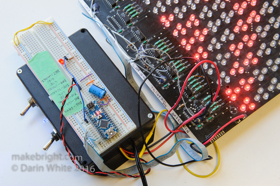
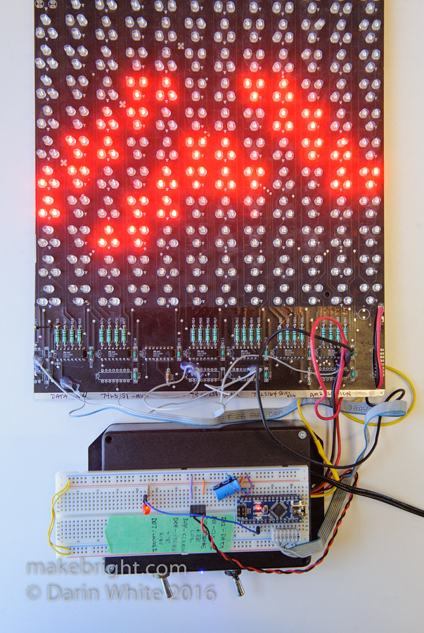
I pulled this old LED sign fragment (upper right) out of the kwartzlab trash five years ago, with every intention of “doing something with it”. It languished long under the bench until I had a free weekend to figure out how it originally worked and how I might make it work again. The dual power supply and Arduino Nano in the lower left were grafted on to relight the LEDs after a couple decades of darkness.
Here’s a short vid of the end result. This scrolling chevron pattern consists of 40 frames which animate the pattern as they are cycled on the display. But that’s software! First I had to figure out the hardware.
Click through for more hacking…

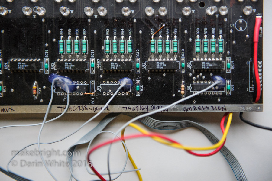
With a little experience, you know that most LED matrices are scanned row by row, forming a stable image by the magic of persistence of vision. So you look for that when you visually inspect the board and start taking notes. The old chips on boards like this are delightfully large and helpfully marked with text labels that often times can be looked up. Looking up the IC U54 by its marking “Micrel 5821BN” we learn that it is an 8-bit serial-input latched driver. The datasheet for that part tells you what the various pins do and helps fill in the blanks in your mental model of the overall circuit. The name of the game is figuring out what connects to what.
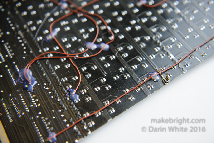
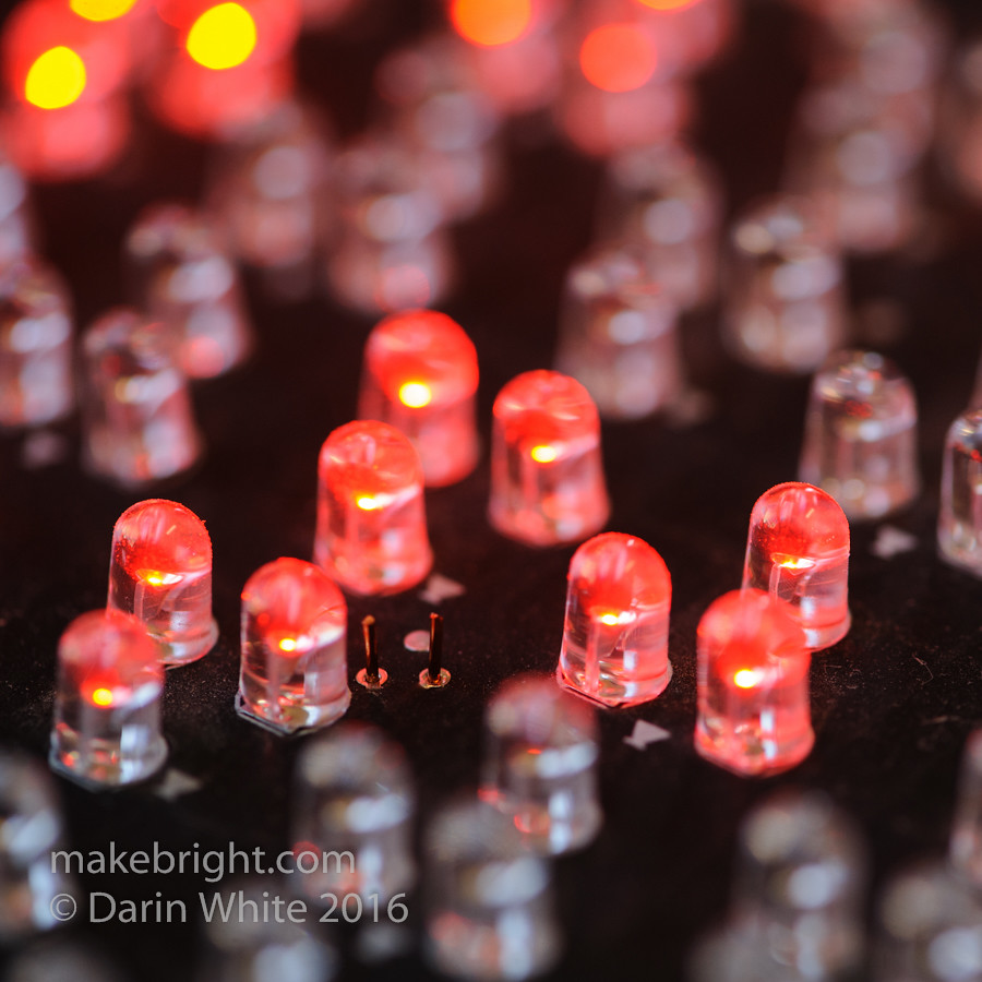
Whomever salvaged this LED matrix from its original installation must have figured the panels would sell better secondhand if they were smaller: so they were cut in half with a table saw. Savage! The repercussions of that decision for me are that a lot of the chips that were originally connected to LEDs are no longer connected (or even present). And vice versa, a lot of LEDs are connected to nothing. So I needed to identify pins I could reroute with this brown copper wire to get a board that once again hangs together. This necessity later makes the bit pattern for driving each row a little gnarly. But that’s software for later.

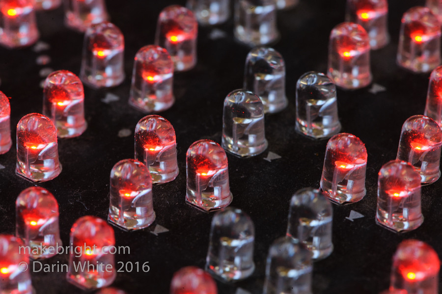
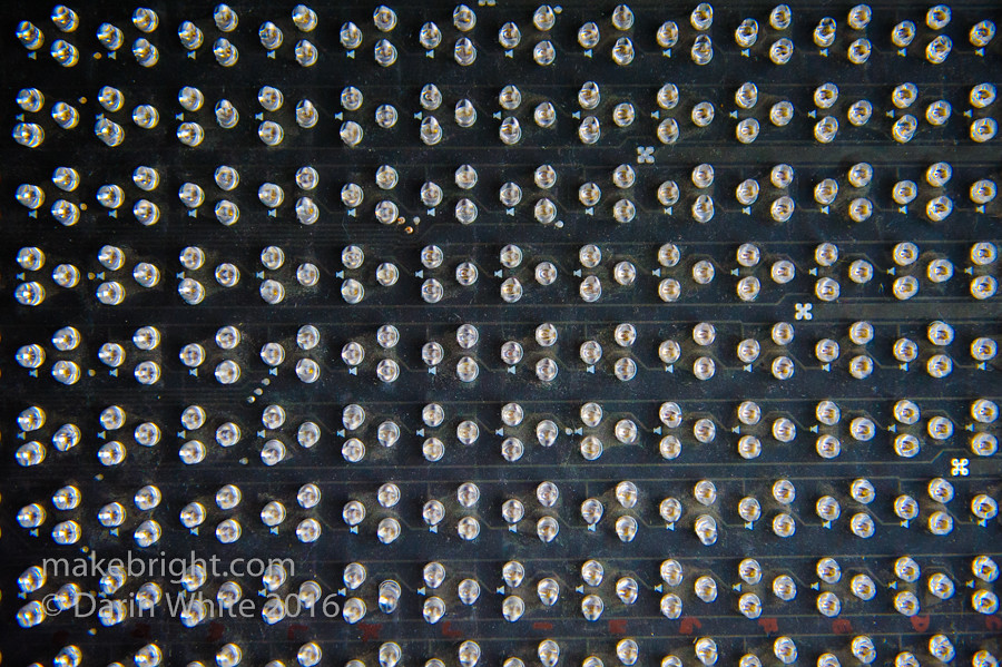
The board markings show it was manufactured in Toronto in 1993. “MODEL MX-1275 REV 1.0” from the board doesn’t help identify the manufacturer. No matter. The “+15V” silkscreen *is* pretty helpful in understanding what voltage to apply to the row drivers. See the black square with a silver tab? That’s labeled “TIP107” and looking that up tells you it’s a PNP Darlington transistor. Those big fat traces coming off each TIP107 pour current into rows of LEDs. Each controllable “pixel” of this board consists of a cluster of 3 LEDs. For the purposes of this discussion, a single row consists of *two* horizontal rows of the 3-clusters. Put another way, applying a logic LOW on the the base of that TIP107 on the right puts current to the top row of 3-clusters and the next row down of 3-clusters. That current drops through the giant flower-shaped via in the bottom right of this photo and…
then runs horizontally on the back side of the board through these fat power bus traces. See? We’ve got 3-clusters above and below each row power bus.
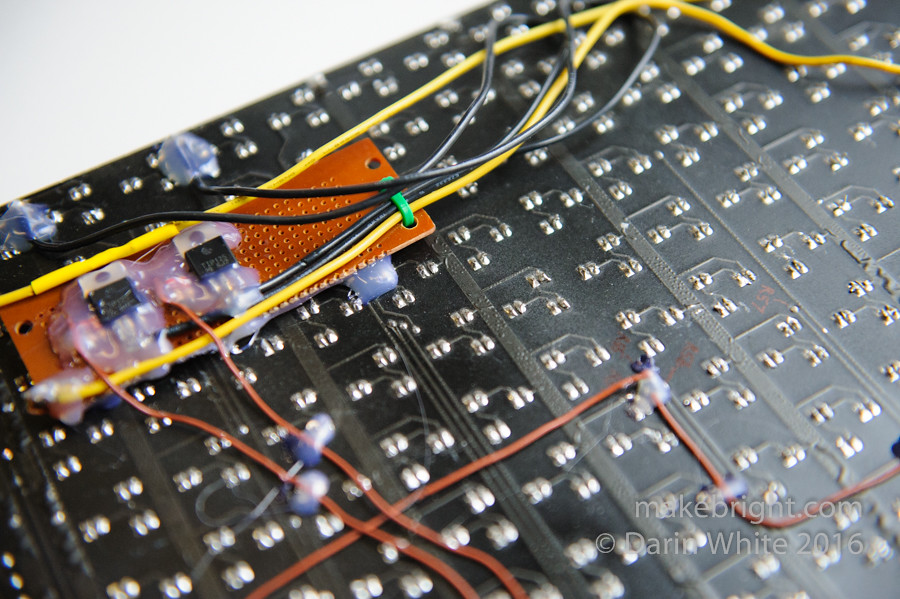
Now due to the unfortunate sawing of the board, a couple of row-driving PNP transistors were absent, leaving the bottom of this board dark without power. Rooting around in my lab I found nothing but NPN transistors to I emailed my pal Dan: “Got any PNP Darlingtons in a TO-220 package? Like a TIP107 or TIP125?” Him: “Yes, I’ll leave some in my mailbox for you to pick up.” High five! I mounted those “Dansistors” on some protoboard and frankensteined that to the back of the panel.
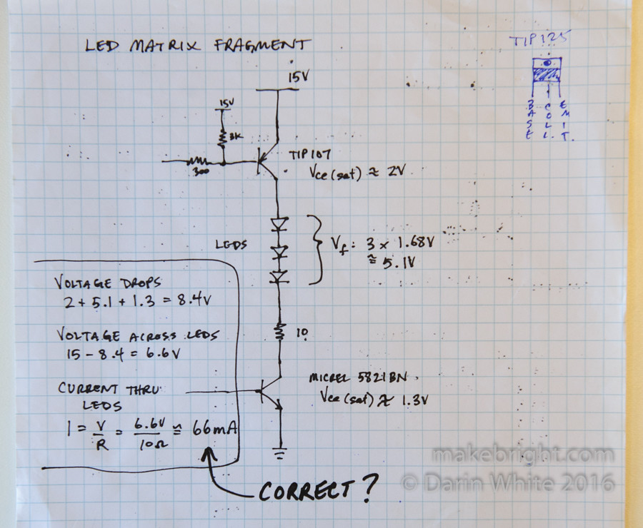
Trying to figure out how much current was going through these LEDs, I drew this schematic fragment to calculate roughly approximate the voltage drops. Too much current through an LED turns it from very bright to forever dark in a heartbeat. I don’t have any specs on the LEDs, but anything north of 30mA for a garden variety 5mm LED leads to a short life. IANAEE, but the figures that came out seemed reasonable. Bear in mind the 66mA LED current is constant. If my software driving this rig runs correctly scanning all 8 rows then the average current through a 3-cluster would be 66mA/8 = 8.25mA. However, software is often buggy, so I figured that in the worst case scenario where my row-refresh routine gets jammed then I can recover from the 66mA overcurrent with a quick flip of the power switch.
Ok, so this matrix has 8 rows x 24 columns of 3-clusters = 192 controllable pixels (less a few lost to the saw). A common control problem of using minimal logic to control numerous outputs. The solution: put current in the top end of one row at a time, and then sink the current that current using these MICREL 5821’s for the LEDs you want lit. Then you turn off the 5821, put current to the next row, and then again select the columns you want lit by sinking current with the 5821’s. If you do this fast enough row by row, then it looks like the whole board is lit at the same time.
There were some other chips along the bottom of the board including a demux and shift register, but I removed them to simplify the addition of the Arduino. I only wanted the power-logic. I opportunistically used those vacant vias to connect up the old board to the Arduino using the grey wires shown. BTW, that’s hot glue you see around the wired connections for strain relief.
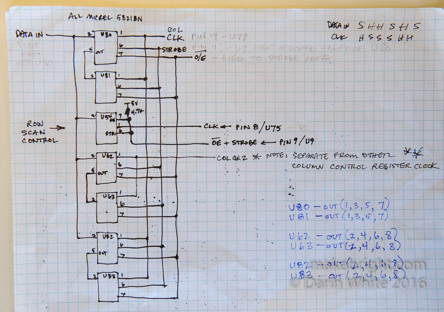
The serial-input latched driver is very useful. Only one data line feeds this whole mess. You just present bit after bit on a single wire. For the driver to accept that bit, you need to take the clock (CLK) line of the chip high and then low. The cool thing is you can chain these drivers together. Above, you’ll see the data goes to the “in” pin 2 of U80 and then after 8 clock cycles starts coming out the “out” pin 5 and then chaining to the “in” pin 2 of U81 below.
The strobe input on these chips forces the data in that serial stream over to the output side of the chip. And finally, the output enable (or OE) input when pulled to ground actually presents those data values on the output pins. It’s easier to explain at a whiteboard.
In the drawing above, the eight outputs of U54 control the power to the eight rows. See the 4.7K pull-up resistor on U54’s pin 7 output enable? The effect of that is that as the board is powering up the row power defaults to off.
I introduced a lot of non-deterministic behaviour by unintentionally leaving the COLCLK2 input floating. The analysis was right. The drawing was right. My wiring was not consistent with either. Once I tied that input to an Arduino output, everything got much saner.
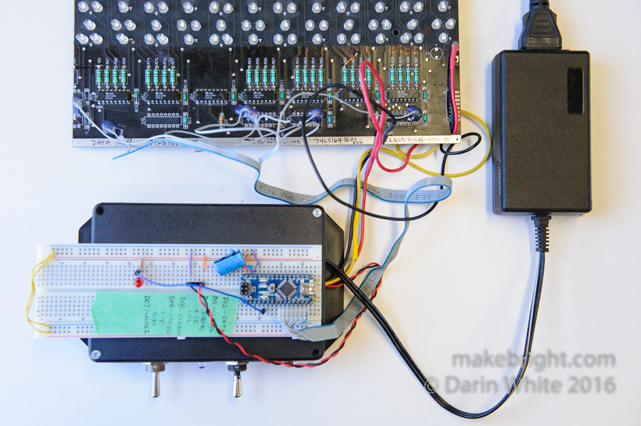
To the LED board, I applied 15V for LEDs and 5V for logic from a cheap switched mode power supply hooked to a power brick. The logic lines from the Arduino were:
DATA
ROWCLK
COLCLK
COLCLK2
ROWSTROBE+OUTPUTENABLE
COLSTROBE+OUTPUTENABLE
From here here it was all software, but first there was a lot of head scratching.
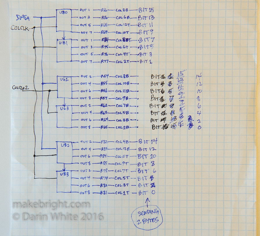
Initially I couldn’t figure out what the 5821’s only used every other output. Seemed like a waste. Maybe to reduce power dissipation? Then I noticed that U80 and U81 used odd outputs and U82 and U83 used even outputs. Feeding in 16 bits of serial data would load both pairs of latches with the same data, but the columns would avoid collision because of this odd/even approach.
Then I wondered about U62 and U63. Why weren’t those column drivers colliding with others? They get the same data in line, but (aha!) they have a different clock line. So with one data line and two clock lines we can set all 24 column drivers. A bit messy, and complicated further by the rewiring required due to the sawing. But we’ll sort it all out in software.
Code and Excel files are on GitHub at https://github.com/darinwhite/LEDmatrix
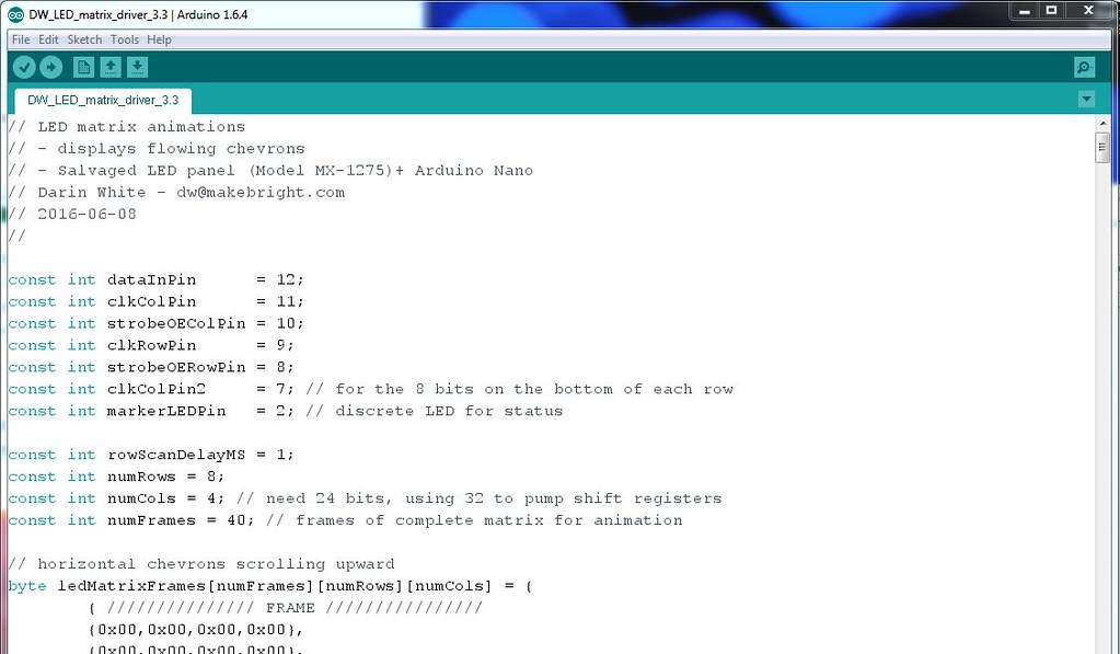
Speaking of software: I started off with some Arduino code to display a static pattern. I used a 2D array to store the pattern: 4 bytes per “row” to cover the 24 columns of LED clusters + extra to pump the shift registers, 8 “rows” of that for the whole panel. Like this:
{ /////////////// FRAME ////////////////
{0x00,0x00,0x00,0x00},
{0x00,0x00,0x00,0x00},
{0x00,0x00,0x00,0x00},
{0x00,0x00,0x00,0x00},
{0x00,0x20,0x40,0x00},
{0xF0,0x40,0x10,0x41},
{0xC,0xA3,0x44,0x14},
{0xF3,0x5C,0x11,0x41}
}
With that working, of course the next goal is animation.
So I flipped to a 3D array to contain the animation frames:
// horizontal chevrons scrolling upward
byte ledMatrixFrames[numFrames][numRows][numCols] = {
    { /////////////// FRAME ////////////////
    {0x00,0x00,0x00,0x00},
    {0x00,0x00,0x00,0x00},
    {0x00,0x00,0x00,0x00},
    {0x00,0x00,0x00,0x00},
    {0x00,0x00,0x00,0x00},
    {0x00,0x00,0x00,0x00},
    {0x00,0x00,0x00,0x00},
    {0x00,0x00,0x00,0x00}
    },
    { /////////////// FRAME ////////////////
    {0x00,0x00,0x00,0x00},
    {0x00,0x00,0x00,0x00},
    {0x00,0x00,0x00,0x00},
    {0x00,0x00,0x00,0x00},
    {0x00,0x00,0x00,0x00},
    {0x00,0x00,0x00,0x00},
    {0x00,0x00,0x00,0x00},
    {0x00,0x20,0x40,0x00}
    },
    { /////////////// FRAME ////////////////
    {0x00,0x00,0x00,0x00},
…}
Because of the rewiring required on the board, there’s not a clean mapping of array bit to LED cluster. I considered shuffling bits on startup to remap a “regular” bit matrix pattern to the one required by this particular matrix. Decided I would pre-process the necessary patterns off-line…
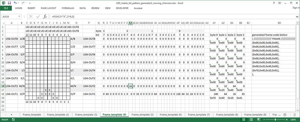
with a gnarly spreadsheet. I know! You put X’s in the grid to specify a frame pattern, which then gets transmogrified into a set of bytes that suit the idiosyncrasies of this LED panel. On the far right we get the Arduino code to copy/paste/compile in the IDE. There are some crude macros included to create/copy new worksheets (which each represent a frame). Another macro consolidates all the frames and drops that text blob of code into the clipboard.
This isn’t particularly elegant, but it got something working quickly. Ideally, I would use an animation authoring tool to create 12×16 animations with onion-skinning, tweening and all that good stuff. Then I could take the output of that and create a processor that shuffles bits for this particular panel.
The code is pretty simple (once you figure out bit and byte order). Above, I defined the 6 output pins to the panel and some parameters of the animation.

Init some variables and set pin mode in setup().

The loop() spends most of the time cycling through the rows of a given frame, and then periodically loads the next frame in the animation.

Some helper functions to push all those bits down the pipe. I think this is the first time I’ve ever used shiftout() which turns out to be extremely helpful here.

I gave a presentation on this project at DevHouse Waterloo #82 back in March (that’s Chris talking in the photo about his thing). This crowd is mostly into software, but based on the questions I got it seems they were interested in a cross-over project like this.
Still to do, I’ve got to fab an enclosure for this rig so it’s a little more mechanically robust. Also planning to do posts on my hw+sw DroneBox project and a foray into NodeMCU modules.
Happy making,
DW
Nice! … and reminds me of some of my early work on v1 of our LED Dance Floor, which was going to do similar row/column clocking into shift-registers for TDM POV stuff. Was going to be WAY too much soldering and we switched to the far easier WS2801 SPI-driven LED chains
The TDM stuff also scares the #### out of me in terms of potentially blowing an entire row at once when stuff locks up. I was considering how to make a minimal watchdog timer from just a capacitor or two and some diodes, connected to the OE.
Tip: The Arduino IDE tells you how much code spae you have used up, but nothing about RAM. A lot of those big arrays are copied to RAM even if you thought they were read only”. Look up Arduino PROGMEM, and also how to find how much(/little) spare RAM you have at runtime. You’ll thank me when you get halfway through coding your first font and wonder why the thing is just strangely locking up – ESPECIALLY if the TDM scares you as much as it scared me 🙂
Nicely done!
NN