5May2009 – old stuff that may still be useful
By request: hooking up a piezo buzzer to the Duemilanove to make sound.
A piezo element is just a bimetallic sandwich, usually circular and stuffed in a small case, that bends when you put a voltage across it. If you alternate between, say, 5 volts and ground across the piezo, then the ensuing bending creates waves in air which we call sound. Some piezo units come with built-in drive circuitry that will create that alternating voltage for you: just hook up power and ground. Most that I salvage are just the piezo element, so I need to provide my own wave.
You can find piezo elements in old modems, fax machines, microwaves, printers, telephones, pagers, PC mainboard (BIOS beep), seatbelt warning buzzers, smoke detectors (triple lead, super-loud piezo with feedback), etc. Pretty much anything that has an annoying beep. You will also find piezos in many dollar store toys, but they are invariably of lower quality. We find tonight’s piezo in a humble modem.
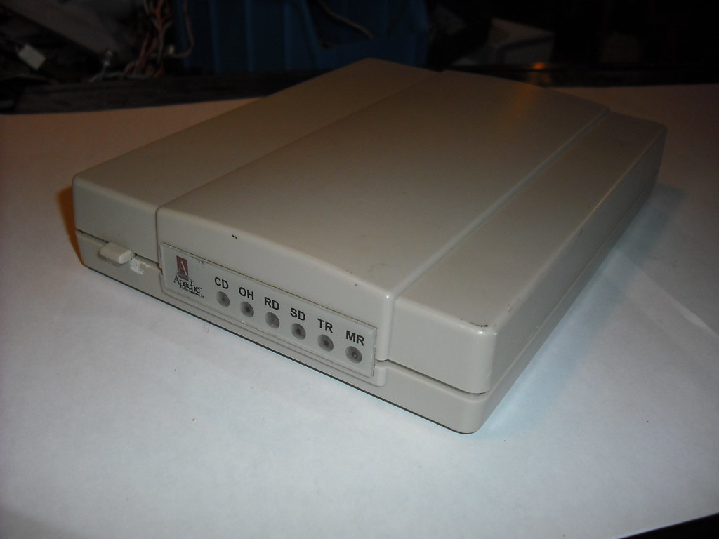
A few Phillips screws later… (I really love this vintage of hardware, early 90’s, beautiful boards, DIP package IC’s, scroungable parts abounding, but I digress)
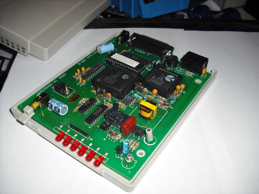
Piezos are pretty easy to spot and can be distinguished from capacitors (the blue things above) by the hole in the top of the piezo package. Here’s ours, it’s the black drum-like thing. Note the 8-pin chip marked “386” just to the left. That’s obviously a LM386 audio amplifier knock-off, and when you look up the datasheet for that chip you see that pin 5 is the output and sure enough that’s what is hooked to the piezo.
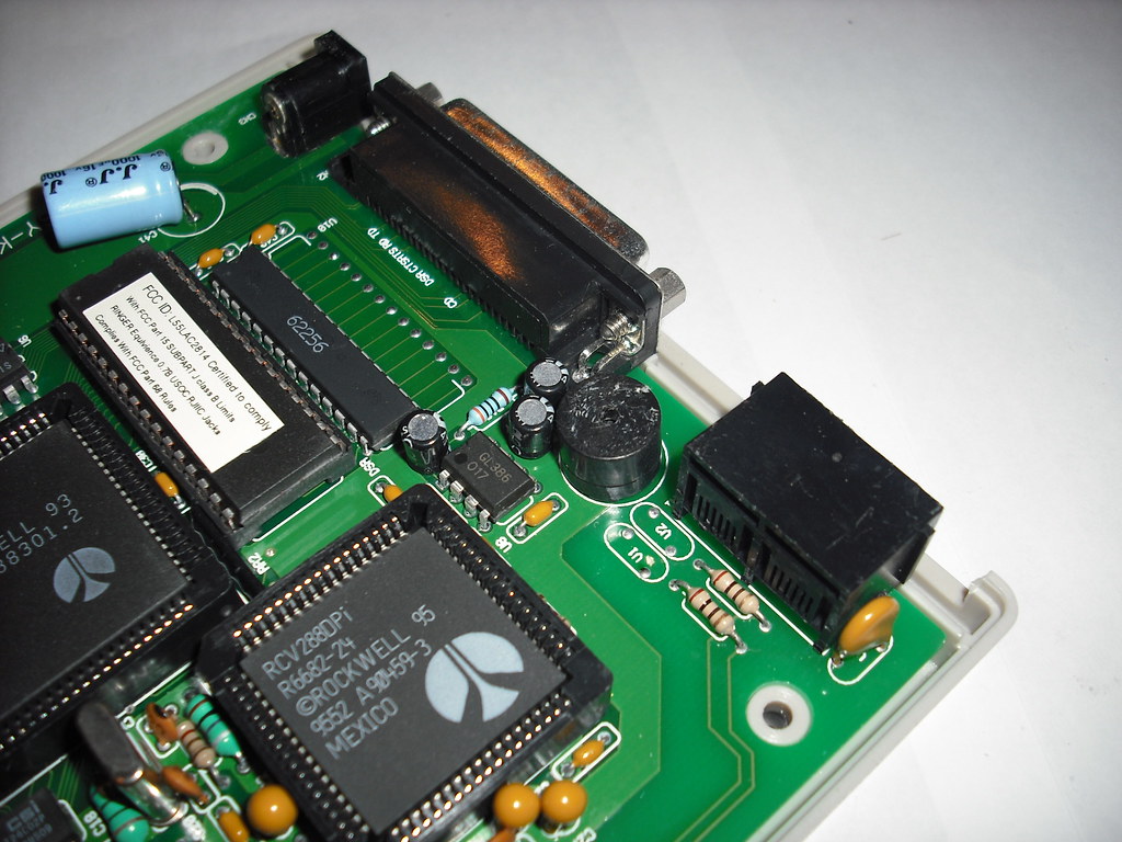
Desolder this part using a solder iron and a solder sucker. Note that it’s sometimes difficult to remove these parts where one pin is connected to a ground plane (the lighter green coloured area). That area is a big sheet of copper that acts as a heat sink, that makes it more difficult to liquify the solder. Too much/too long with the heat and you kill the part, not enough heat and you end up pulling a pin off the piezo. Just takes a little practice/patience.
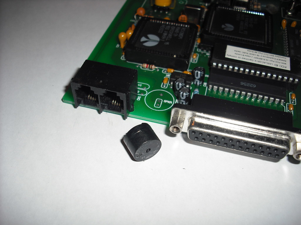
There’s a small black electrolytic capacitor to the right (above) of where the piezo was. Looking at the board we can see that the piezo is hooked to the 386 amp, not directly, but through the capacitor. I understand this is best practice, probably so the piezo doesn’t stay bent for any length of time when in the no-sound state. So we’ll do the same thing on our little rig for the Arduino: use a cap (salvaged from something else, likely a VCR). Also note this piezo is handily marked with a + sign indicating polarity. I’ve hooked them up either which way before and not had problems, but I’m sure there’s some reason for this marking.

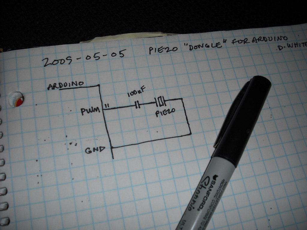
And hook it up something like this (see, labbook again, eh?). Disregard the pin number 11 there. I was going to get into the pulse width modulation (PWM) to make the sounds, but just ended up using the Arduino-provided sound sample sketch that hooks to pin 9 instead. I should have also put the customary little + sign to indicate which way to hook up the cap (+ toward the Arduino, – toward the piezo). Oddly, we always show a + sign in schematics, but every electrolytic cap ever made is labelled with the – sign. Hmmm…
A little careful soldering and some more PC-gut wire…
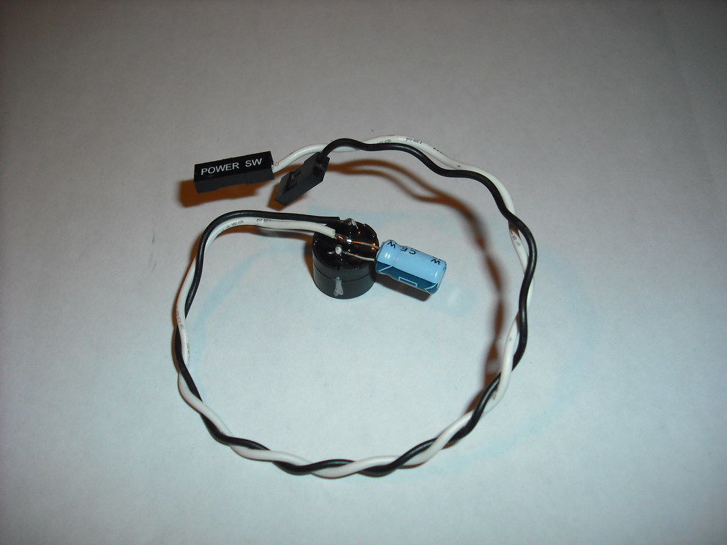
Note it’s easy to swap wires around on the PC-gut wire harnesses (show above). You just lift the little tab that keeps the crimped connector inside the plastic shell, and the wire slides right out. You can mix and match them however you like. This is far-easier to demonstrate than describe.
And all hooked up to Gnd and pin 9 we have…
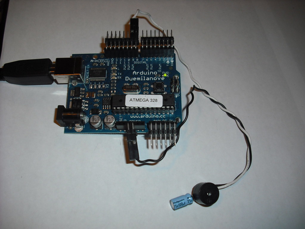
Load the Arduino-provided example sketch from Digital/Melody to hear the tune.

Piezos come in all shapes, sizes, and colours, so be on the lookout and scrounge away.
A few things I’ve learned along the way about piezo elements:
- the plastic case provides a resonant cavity to make the sound much louder, so case-on is often preferable
- different types of piezos have different resonant frequencies, i.e. the frequency at which they produce the loudest sound. Often times that is around 4kHz, which is where the human ear’s sensitivity is also peaked[cite]. When buying new you just look this up on the datasheet. When scrounging, you write an Arduino sketch that sweeps through frequencies (say 1.5kHz to 3.5kHz) while you listen for the loudest perceived sound. Piezos do their best work right around their resonant frequency, which leads to really terrible tinny sound quality outside of that range, so sometimes you need and honest to goodness speaker depending on your application.
- piezos can work in reverse too, i.e. bending the piezo produces a voltage. You can use a piezo as a “tap” sensor. Think electronic drums, or collision sensor for toys.
- soldering lead wires to raw piezo elements to use them as tap sensors is really tricky. I suspect that silver-loaded conductive epoxy might be the way to go here, but it’s not cheap.
Note to Daryl: my good friend Daryl suggested I need to provide more context in these posts to explain, for example, why someone might want to hook up a piezo to an Arduino. Why? After a little reflection, I have two observations:
- I have no function-guilt (that compelling feeling that your creation must “do” something). I am a context-free maker. It’s a BYOC party.
- Functional fixation (described by a guy named Mudge at Defcon years ago) is a terribly limiting effect. If I tell you this piezo hookup is for an Arduino-based birthday card that plays Tom Waits songs, then that statement sort of mentally masks out the millions of other applications.
Thanks for the suggestion, Daryl. It made me think harder.
A request: if you like these posts, please come out and talk to me in person at the MakeKW social meetup on Thursday May 7 at Zeke’s. I’d like to get your input on the hackerspace requirements survey we’re doing there.
DW